Controls
Helm Pumps (Model H)
Brochures
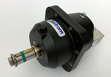
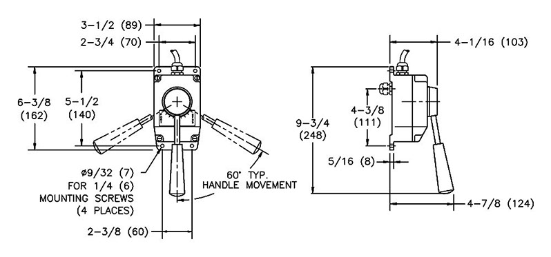
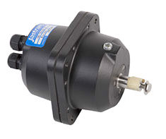
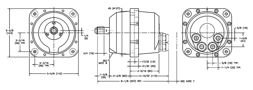
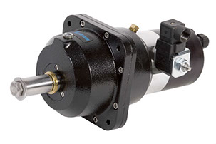
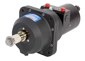
Model HThe H pumps are designed to operate in “non-pressurized” hydraulic systems requiring only two lines from the helm pump to the cylinder. The Model H helm pumps include the following standard features:
- An external lockvalve to isolate with helm and prevent rudder feedback
- A pressure rating for the lockvalve of 1,875 PSI
- A powder coated, high strength cast aluminum housing which provides corrosion and abrasion resistance
- A flexible mounting pattern allowing any angle between the vertical and horizontal axis
- An internal capacity to act as a small vented oil reservoir
Jog Lever (JO100 / JO300)
Non Follow-up (NFU)
Brochures
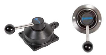
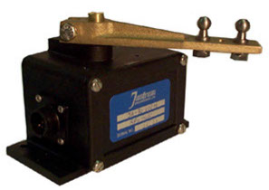
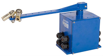
Analog Input DevicesThe Jastram Jog Lever provides non follow-up (time dependent) electric control. Jastram Jog Levers operate either completely on (as long as the switch is activated) or completely off (when it is released).
- Compatible with all Jastram’s electro-hydraulic steering systems and most third party autopilots
- Four versions available:
- JO100-1 contains one set of microswitches
- JO100-2 contains two sets of microswitches
- JO300-1 yacht styling with one set of microswitches
- JO300-2 yacht styling with two sets of microswitches
- The spring loaded jog switch returns to center when released (The rudder remains where positioned when the lever is released)
- Waterproof and corrosion resistant housings, with an IP 66 rating
- Supplied with 5ft (1.5m) of cable
Cable Requirements: 18 AWG, 3 Conductor, Standard Copper wire
Voltage: 12, 24 or 36 VDC
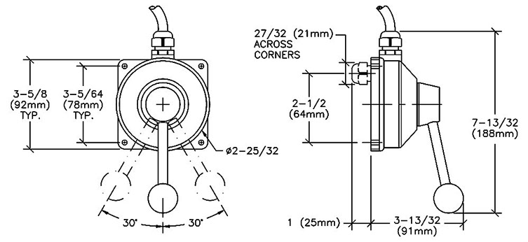
Diagrams for JO100 / JO300:
Lever Controllers (LC100 / LC300)
Full Follow-up (FFU)
Brochures
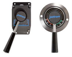
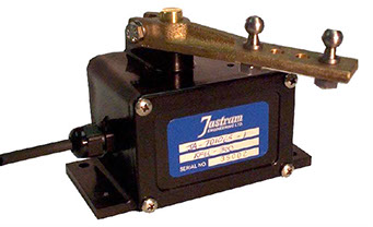
Analog Input DevicesThe Jastram Lever Controller provides full follow-up (way dependent) electric control.
When the steering lever is moved to the desired rudder angle, the rudder will follow-up to the position requested b the lever.
- Smoother and more accurate steering than jog steering
- Compatible with all Jastram Full Follow-up steering systems and most third party autopilots
- The rudder position is displayed by an indicator strip below the lever arm of the LC.
- Four versions are available:
- LC100-1 produces one output signal
- LC100-2 produces two output signals – the second signal controls a second amplifier or an alarm circuit.
- LC300-1 yacht styling; produces one output signal
- LC300-2 yacht styling; produces two output signals – the second signal controls a second amplifier or an alarm circuit.
- Waterproof and corrosion resistand housings, with an IP 66 rating
- Supplied with 5ft (1.5m) of cable
Cable Requirments: 18 AWG, 3 Conductor, Standard copper wire
Voltage: 12 , 24 or 36 VDC
Diagrams for LC100 / LC300:
Electric Wheel (EW 200)
Full Follow-up (FFU)
Brochures
Analog Input DevicesThe EW provides full follow-up electric wheel control. When the traditional steering wheel is turned the EW produces an analog rudder command signal. The rudder will then follow-up to the position commanded by the movement of the wheel.
- Compatible with all Jastram Full Follow-up steering systems.
- Standard shaft size for customer supplied wheel
- The EW200 provides 4 turns lock to lock
- Multiple output signals are available to control a second amplifier or a rudder order indicator
- Steering wheel “feel” is adjustable
- The Internal mechanism is protected by a slip clutch to prevent damage to the unit
- Rudder Order Indicators driver boards are optional
- ROI’s are recommended so the helmsman knows where the rudder will follow-up to
- Waterproof and corrosion resistant housing, with an IP 66 rating
Recommended Cable: 20 AWG, 3 Conductor, Standard, Copper wire
Shaft Size: Stainless steel shaft with ¾” shaft, 1:12 Taper
Voltage: 12, 24 or 36 VDC
Diagrams for EW 200:
Digital Wheel (DW)
Brochures
Digital Input DevicesDigital Wheels are unique input devices which provide full follow-up digital electric control. The two main features of the Digital Wheel over the standard electric wheel are:
- A programmable number of wheel turns from ¼ to 10 turns lock to lock.
- When taking over control of the steering system the Digital wheel takes over at the present position of the rudder.
Under power steering, the steering wheel is turned producing a rudder command signal. The rudder then follows up to the position requested by the wheel.
- Only compatible with Jastram Digital steering systems
- Two version of te DW are available:
- DW-1 is the standard unit and produces one output singlan
- DW-2 produces two output signals – the second signals for control redundancy, or for operation of a second steering system where independent twin steering gears are installed.
- Effort to turn the wheel does not change regardless of operating conditions
Steering Wheel: The wheel is not supplied with the digital wheel.
DW shaft dimensions are: 1” by 1 7/8” shaft with a ¼” square key
Output Voltage: 12 or 24 VDC
Recommended Cable: 16 AWG 2 wire, not shielded
Digital Helm (DW)
Full Follow-up (FFU) / Manual
Brochures
Digital Input DevicesThis patented hybrid hydraulic / electric unit provides full follow-up digital electric control as well as emergency manual hydraulic control. Under power steering, the steering wheel is turned producing a rudder command signal the rudder then follows up to the position requested by the wheel. In the event of a power failure the digital helm seamlessly transfers to manual hydraulic steering. Under emergency manual hydraulic steering the numbers of turns depends on the size of the actuators.
- Under power steering mode:
- Adjustable number of wheel turns, programmable from ¼ turn to 10 turns lock to lock
- Effort to turn the wheel does not change regardless of operating conditions
- When taking over control of the steering system the Digital wheel takes over at the present position of the rudder. Other systems usually move the rudder back to center before acquiring control of the steering.
- Capable of Manual steering
- Compatible with the Jastram Digital steering system. The Digital Helm generates a digital signal to Jastram Steering Control
- To be used in conjunction with Digital Helm Manifold (DHM)
- Wheel is not supplied with the digital helm
Digital Helm Manifold (DHM)
Brochures
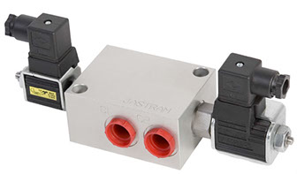
Digital Input DevicesThe Digital Helm Manifold (DHM) is a small, compact manifold which provides seamless transfer from fly-by-wire steering to emergency manual hydraulic steering in the event of a power failure.
- To be used in conjunction with the Jastram Digital Helm
- Within certain parameters, a single DHM can service Multiple Digital Helms
Input Voltage: 12 or 24 VDC
Recommended Cable: 16 AWG 2 wire, not shielded
Rudder Feedback Unit (RFU 300)
The RFU 300 is built to resist water and damage caused by vibrations from rough seas and mechanical systems. The RFU 300 features a high quality, long life potentiometer with heavy duty gears. Designed to be used only with the RAI Panoramic 3300 and RAI 301/RAI 300
- Up to three indicators can operate at the same time
- Unit operates on any voltage between 10-32 VDC
- Comes with 50’ cable
Rudder Feedback Unit (RFU 400)
The RFU 400 is built to resist water and damage caused by vibrations from rough seas and mechanical systems. The RFU 400 features a high quality potentiometer with heavy duty gears, and a built in electronic driver board. The addition of the driver board in the unit eliminates the need for a 301 Indicator Designed to be used with the RAI 300.
- Up to five indicators can operate at the same time
- Unit operates on any voltage between 10-32 VDC
- Waterproof design with unique double sealed shaft and waterproof quick connect cable plugs
Rudder Feedback Unit (RFU 2000)
The RFU 2000 is built with cast aluminum and stainless steel and designed for heavy duty use in both commercial and pleasure crafts. Two types of devices are available for the RFU 2000 to generate the feedback signal: the standard is the potentiometer type, and second would be the optional contact free Hall Effect. All electronic circuitry necessary to develop rudder feedback signal and rudder angle signal is contained within the RFU 2000. The RFU 2000 outputs both a rudder angle indicator signal and rudder feedback signal, as well as an optional second independent second rudder angle indicator signal.
- Built in set of adjustable limit switches (an optional second set of limit switches is available).
- Unit operates on any voltage between 10-32 VDC
- Waterproof design with unique double sealed shaft and waterproof quick connect cable plugs
Hydraulic Follow-Up (HFU 360)
Brochures
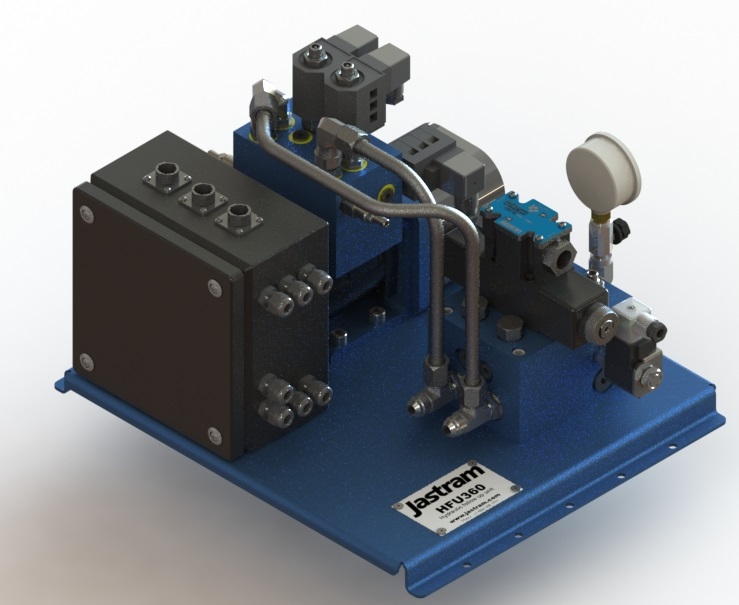
HFU360-8The HFU360 is a state-of-the-art electro-hydraulic steering system, providing full follow-up power steering with unmatched smoothness, quietness and accuracy for small to medium size vessels.
- Small, lightweight unit (18x16x13 in, 25 lbs) (457x406x330 mm, 24.9 kg)
- One or multiple helm pump stations provide FFU effortless power steering
- Optional electric controls by jog levers and/or autopilot
- True changeover to manual steering in case of electric power failure, pumpset failure or cable breaks
- Hydraulic protection by double relief and load holding valves
Power Supply : 24 VDC, 6 A
Flow Rate: 8 GPM (Max)
Working Pressure: 1500 psi (Max)
Rudder Indicators (RAI/ROI X80)
Brochures
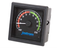
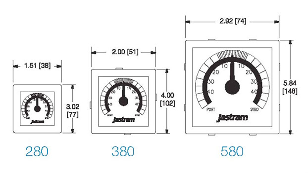
Rudder Angle IndicatorsThe X80 Series Rudder Angle Indicators are produced to fill the requests of Vessel operators and to meet Classification Societies requirements. The X80 Indicators come in 3 sizes to fit all bridge applications. Up to five indicators can be used with a mixture of forward and reverse scale meters.
- Wheelmark and MED Approved
- Designed to be flush-mounted for panel or console
- X80 series are rated for IP52 Protection
Power Supply: 24 VDC Max 180mA
Recommended Cable: 18 AWG 4 wire, shielded
Diagrams for RAI/ROI X80:
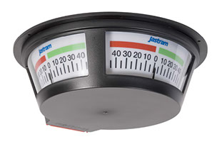
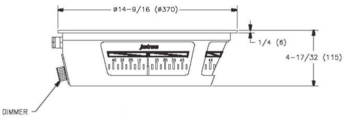
Panoramic Rudder Indicator (RAI 3300)
Brochures
Rudder Angle IndicatorsThe Largest of the Indicators is the 3300 overhead three faced panoramic indicator. These are stand alone systems comprised of three main components:
- A three faced panoramic Rudder Angle Indicator (RAI 3300)
- RAI 3300 power Supply
- Rudder Feedback Unit
- Built in dimmer allows for adjustment of the backlight
- Deckhead mounted at any convenient location in the wheelhouse
- Two Power Supply options are available:
- Input voltage of 12-24 VDC and outputs 24 VDC
- Input voltage of 100-40 VAC and outputs 24 VDC
- Cable requirements 16 AWG, 3 wire, shielded
Diagrams for RAI 3300:
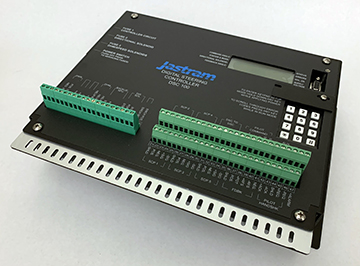
Digital Control Amplifier (DCA)
Brochures
DCAThe new Jastram Digital Control Amplifier (DCA) is specifically designed for small to mid-size commercial vessels and pleasure crafts. As its larger cousin the DSC, it relies on state-of-the-art digital technology for fast and accurate steering controls, in a small and simple design.
Up to eight input devices can be connected to each DCA. These input devices can be Non-Follow-Up (jog switch), Full-Follow-Up (lever control-ler or electric wheel), Digital (Jastram digital helm pump) and an addi-tional interface to autopilot is provided.
The DCA is the controller between the rudder command and the steering hydraulics. It will convert the command from any input device to a smooth and accurate rudder motion.
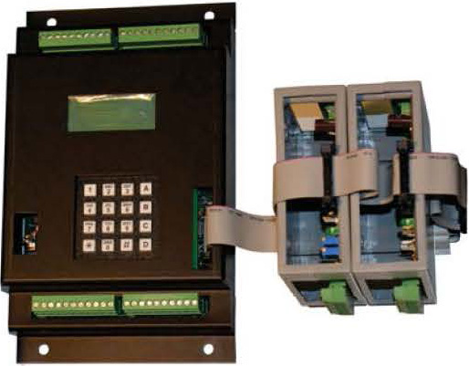
Digital Control System (DCS)
Brochures
DCSThe Digital Control System consists of four basic components:
- A Digital Steering Controller (DSC)
- At least one Mode Control Processor (MCP)
- At least one Steering Input Device
- A Rudder Feedback Unit (RFU)
The core of the Jastram Digital Control System is the Digital Steering Controller (DSC). The DSC processes signals from the Mode Control Processors (MCP) and in turn controls the response of the hydraulic power units and, ultimately, the rudder. The MCP is a station processor which connects the signals from the station Input Devices and Control Panels to the DSC.
Control Panel (CP375, CP600)
Brochures
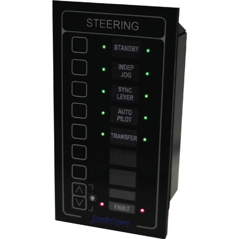
Control PanelsThis unit provides direct button selection of the available steering control modes. It is configured for each system installation. Mode selection is located at every steering station as required by Classification Societies.
- Selected mode of steering is illuminated
- Control Panel face is backlit and includes a built-in dimmer control.
- Fault light and audible alarm are built in
- Black Lexan face panels are:
- 3 in. (76mm) wide by 6 in. (152mm) high, or
- 3 in. (76mm) wide by 3 3/4 in. (95mm) high
- Panels are water resistant from front.
- Selection panels can also be supplied by others for integration into an integrated bridge
Motor Starters & Alarms
Motor Starters (MSA 100, 200 & 300 series)
Brochures
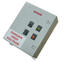
Motor Starter & Alarm SystemsThe Motor Starter & Alarm (MSA) systems control and monitor the function of hydraulic power units. In essence, they start and stop the electric motor which drives the hydraulic pump powering the steering gear. The MSA comes in 3 series:
- MSA 100 – Basic Motor Starter only (no Alarms).
- MSA 200 – Basic Motor Starter + Alarms to meet certain classification requirements.
- MSA 300/301 – Basic Motor Starter + additional functions and complete Alarms to meet classification requirements.
- The MSA system is designed to meet all major Classification Societies requirements.
- Each MSA box services one Hydraulic Power unit.
- The MSA box connects to multiple remote alarm panels
- MSA motor interlocking prevents two motors, connected to two MSA units, from being run simultaneously.
- Automatic transfer to backup power supply upon failure of primary power keeps the steering alarms active
- Automatic restart timer
- Visual indicators at both local and remote panels to warn of events taking place in the steering system.
Options:- VDR interface can be added to MSA system for Class requirements
- Ship’s AC Supply output for Dehumidifier in HPU motor
- Serial Output for third party systems, i.e., Ship’s Central Monitoring System
- Ammeter, Hour Counter, Engineer’s Delayed Alarm, Hydraulic Lock Alarm
Alarm Panels (AP 375, AP 600)
Brochures
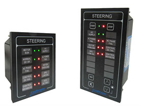
Motor Starter & Alarm SystemsAP-375, AP-600
These customized panels provide visual and audible alarms at both local and remote stations.
- Dedicated Pushbuttons to test and silence the Alarm Processing Units.
- Dedicated buttons for dimming and brightening the backlighting
- Push buttons and Indicators options include:
- Up to 11 standard steering gear alarms and Indicators
- AP 375 can be designed with up to 9 buttons
- AP 600 can be designed with up to 18 buttons
- LED visual indicators display normal operating and failure modes
- Motor start and stop capability
Hydraulic Powerpacks
Hydraulic Power Units (HPU)
Brochures
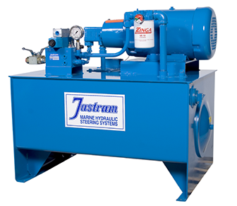
HPUJastram designs and manufactures custom Hydraulic Power Units (HPU) to meet a wide range of requirements. Powerunits are available to meet specific design challenges or requirements of the vessel owner, naval architects or shipyard. Jastram HPU’s come in either On/Off type to help meet budget requirements, and proportional type for a smooth & quiet steering control.
- Specially designed and built for Marine Environment
- Custom tank shape and capacity
- Customizable motors, manifold, and paint scheme
Engine Driven Systems (PTO)
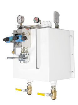
For those vessels where space is a large concern. Jastram steering systems can be offered with an Engine driven type of unit which consists of a pump that couples onto the existing main engines and provide flow to a custom wall mount reservoir assembly. This set-up would be used in lieu of a Hydraulic Power unit set-up.
- No need for Motor Starter and Alarms
- Custom tank size available
- Custom pumps, manifold, and paint.
Steering Gear
Brass Model Cylinders (B series)
Brochures
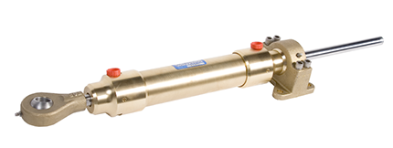
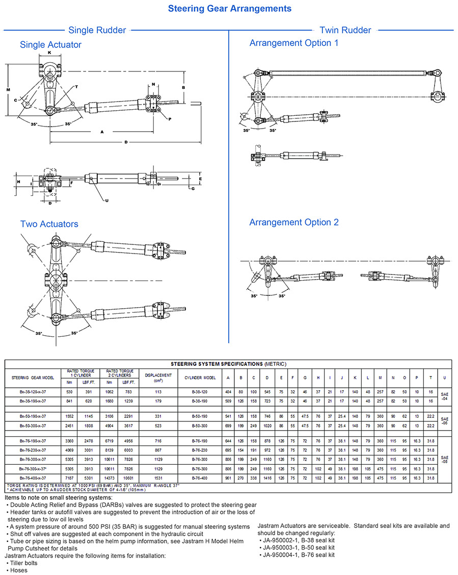
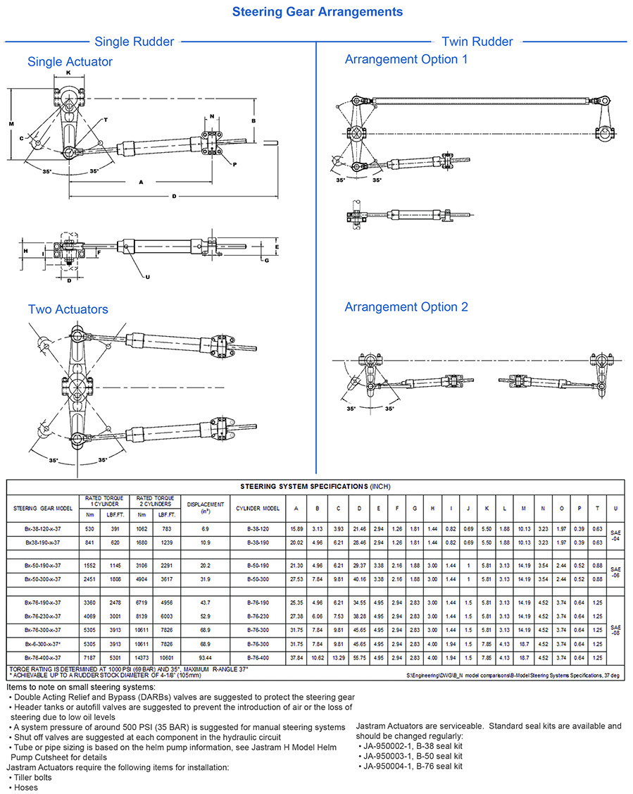
Model BJastram B Model Actuators are double-acting equal displacement cylinders which are directly connected to a tiller. Designed for continuous heavy duty operations for the marine environment. The B Model Actuators are type approved by Key IACS members (please contact Jastram for most up to date list).
- Designed with self-aligning stainless steel spherical trunnion and rod end bearings for easier installation
- Low friction seals for smooth movement of stainless steel cylinder rod even under relatively light loads
- Bleed ports located at each end to facilitate rapid system fill and purging.
- Cylinder can be removed without removing trunnion.
- Threads protected from outside air by O-ring providing better corrosion resistance and therefore easier maintenace.
- JEL rod end and trunnion assembly have oversized bearing areas providing superior durability even under harsh loading conditions.
- JEL uses floating seals for the piston rod providing unsurpassed sealing and easy maintenace.
Diagrams for Brass Model Cylinders (B series) – Metric:
Diagrams for Brass Model Cylinders (B series) – Imperial:
Steel Model Cylinders (S series)
Brochures
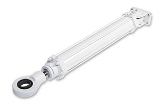
Model SJastram S Model Actuators are specifically certified for use in commercial marine hydraulic steering systems. Their rugged steel construction includes many standard features resulting from our long experience in the manufacture, operation and service of steering systems.
- Micro-honed heavy wall cylinder barrel
- Precision ground, chrome-plated piston rod
- Tie-Rod construction using re-usable steel tie-rods
- Self-aligning spherical bearings
- Designed with higher pressure rating (2400 psi vs 2000 psi) than those of competitor, facilitating more compact systems than those of our competitor
- JEL using cast steel for Rod End, Tail and Head – cylinders are more compact.
- JEL cylinders designed with extended neck for the rod end – thread connection to the rod end is more strong.
- JEL cylinders provided with adjustable seals on Head – easy to fix problem with leakage at the seal.
- JEL uses steel tie rods – better elongation, better serviceable and can be used after cylinder refit.
- JEL cylinders required less space for the same stroke as competitors.
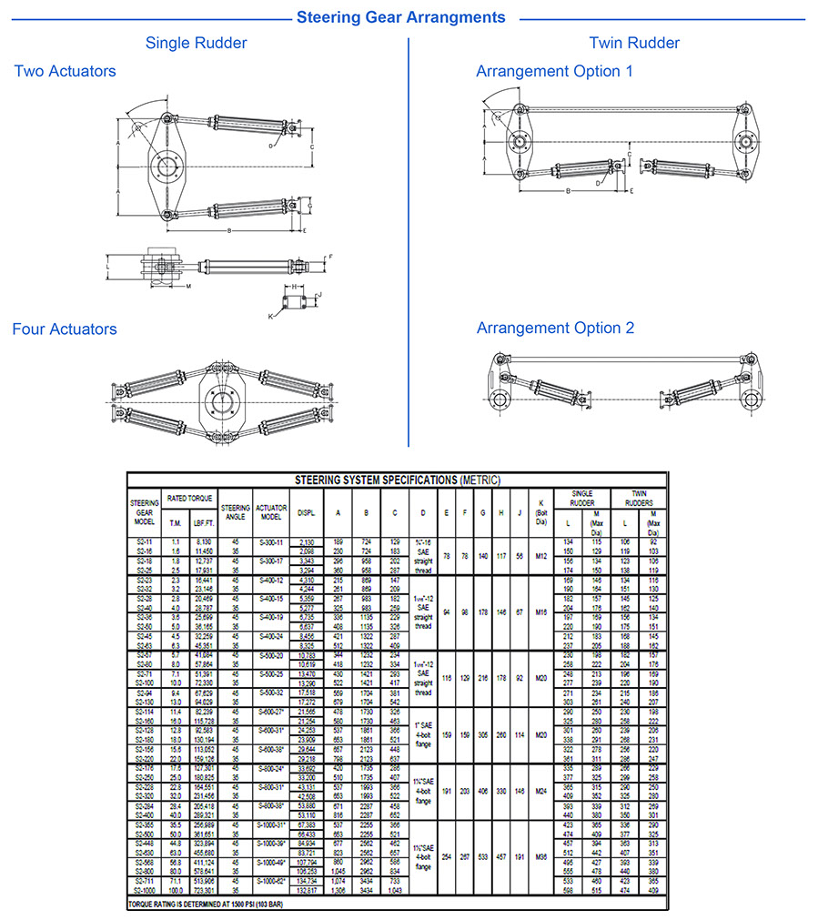
Diagrams for Steel Model Cylinders (S series) – Metric:
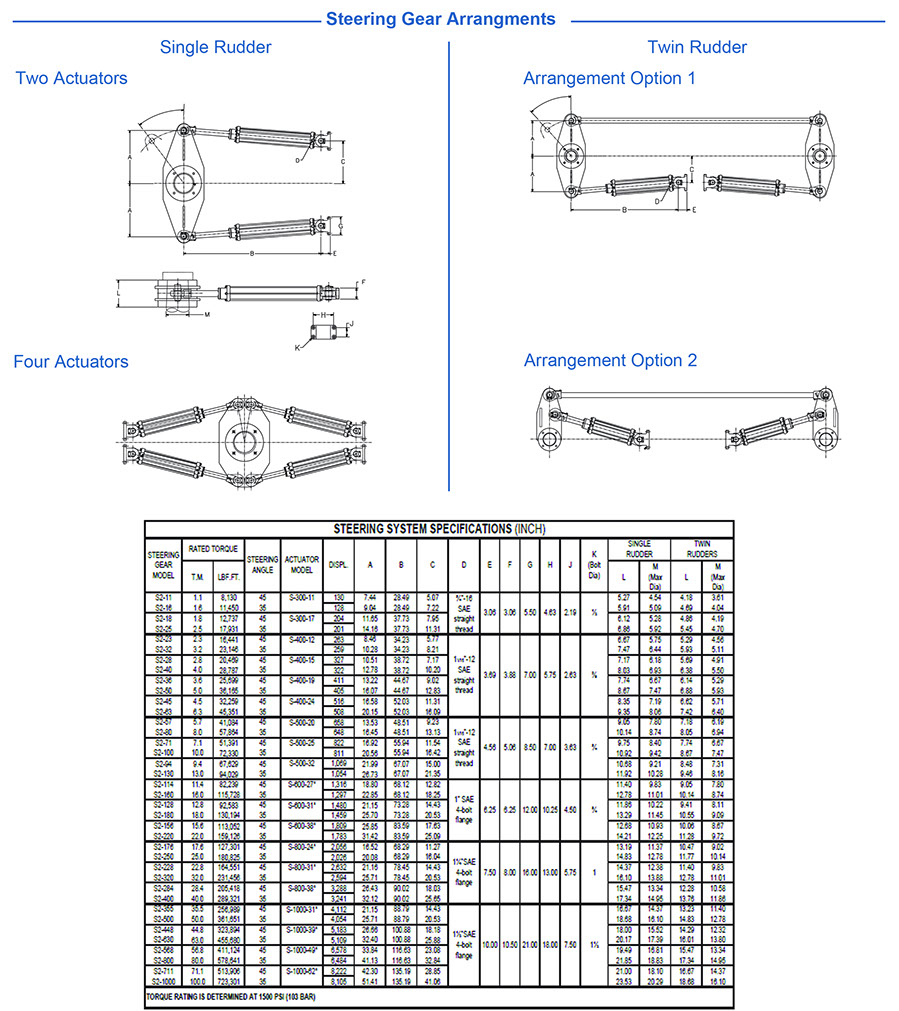
Diagrams for Steel Model Cylinders (S series) – Imperial:
Frequently Asked Questions
Everything you need to know about Jastram’s services.
Q. Where can I order replacement parts and equipment?
A. Jastram parts and equipment is available through our worldwide dealer network. Please contact your local Jastram dealer or e-mail Jastram at parts@jastram.com
Q. Where can I have my Jastram equipment serviced?
A. Jastram equipment can be serviced through our trained dealer network. Please contact your local Jastram dealer or e-mail Jastram at parts@jastram.com.
Q. How can I obtain technical support for my Jastram steering system?
A. Jastram has a team of trained staff standing by to offer support. Please contact Jastram service at parts@jastram.com.
Still have questions?
Can’t find the answer you’re looking for? Please contact our friendly team.